This buck converter/step down circuit is based on KA7500c SMPS controller chip,
the following circuit is from the reference design you can find the details of the circuit and calculations from the document. This is one of the application circuit built around with KA7500C, this buck converter can suply a load current of 5.75Ampere at 5V we could also use TL494 or KA7500c both are same in operation/ratings. The recommended operating voltage range is 7V to 40V DC and the power source i am using for this is a old laptop power supply adapter rated 18V,3.7A. , however the maximum input current the circuit draws is 2A at full load.
circuit diagram:


buck converter can supply load current of 5.75A at 5V and the short circuit current is 7Ampere. the maximum output is 5V×5.75A, the ripple voltage at max power out is 94mV and input power is 18V×2A and the efficiency(η) calculated
η = output power/input power = 5×5.75/18×2
η = 79.86%
Note: C1,C2,C3 are the low ESR electrolytic capacitors add 2 of 100nF,50V rated ceramic capacitors in parallel to C1,C2,C3, to reduce the high frequency noise.
L1, FS-1RN series toroidal cores made from iron powder (26) for creating inductors, FS-1RN core or similar you can get this one from old desktop PSU’s. here is a useful link of toroids, one of my friend Mr William helped me in selecting toroidal core, thanks to him.
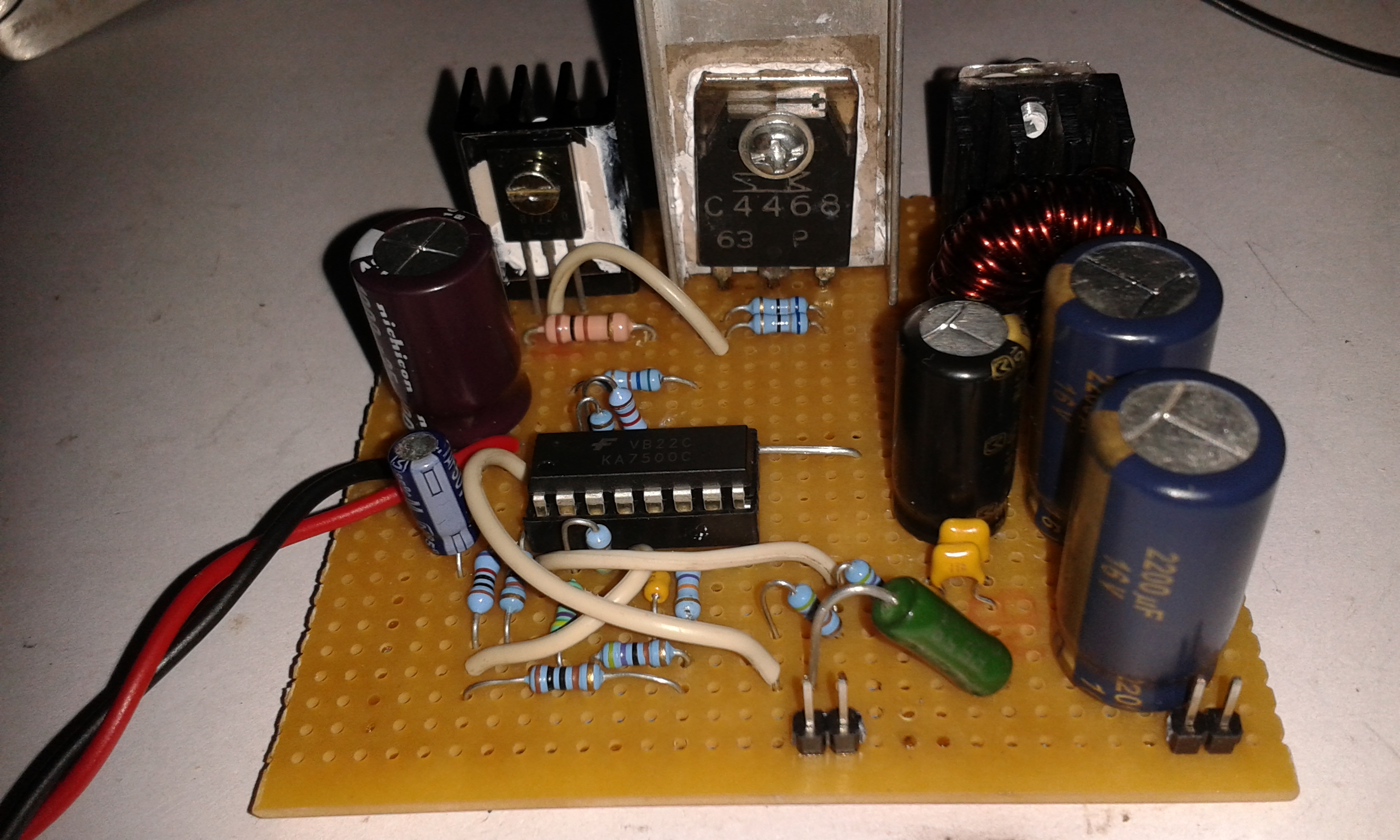
Q1 , Q2 are2SB772 2SC4468 they are audio transistors, can be used for switching applications, linear.
