Wireless power transmitter and receiver//

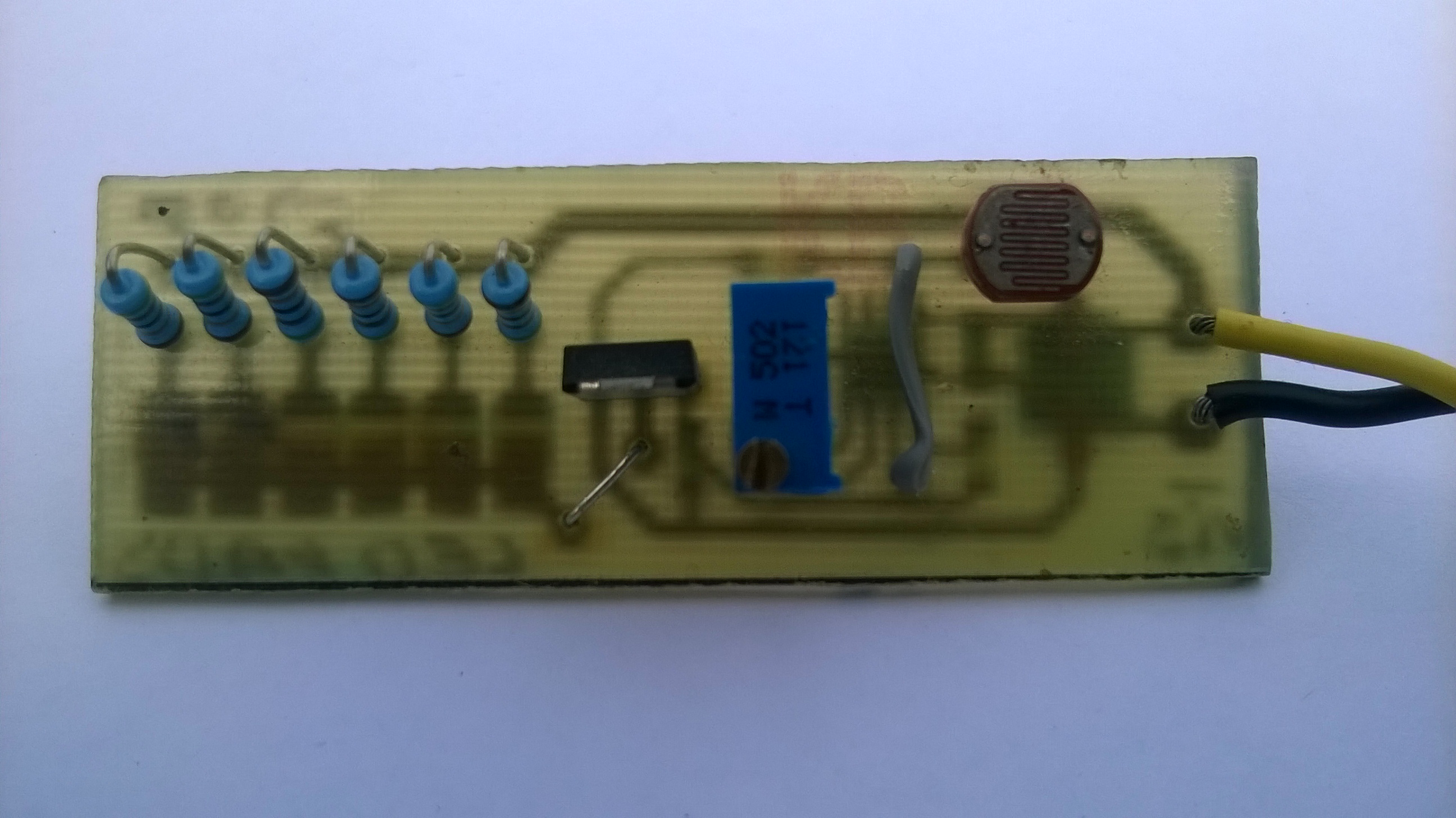
working model of wireless power transmitter and receiver.  The Transmitter and Receiver coils with capacitors connected to each coils, forms a tank circuits that resonates with a frequency of f = 1/(2π√(LC)), if the two resonant circuits resonating at the same frequency and were brought to close, the energy  transferred from transmitter to receiver…

so, the frequency of transmitter and receiver must be tuned for different inductance values of transmitting coil and the receiver coil…

L1 = 10turns , 160mm dia  of 18SWG (transmitter coil) = 35.826uH

L2 = 20turns, 160mm dia of 18SWG(receiver coil) = 131.48uH

i have calculated the inductance of Tx and Rx coils using oscilloscope and the pulse generator.
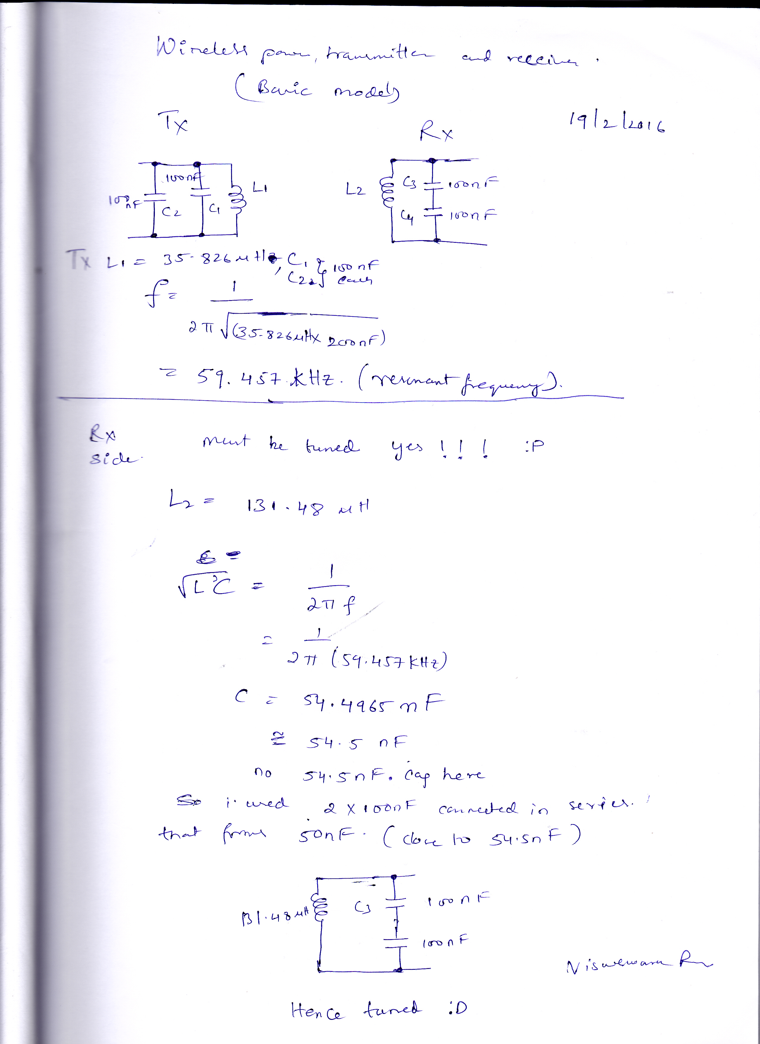
paper work:

paper work


schematic:

WP Tx Rx
circuit

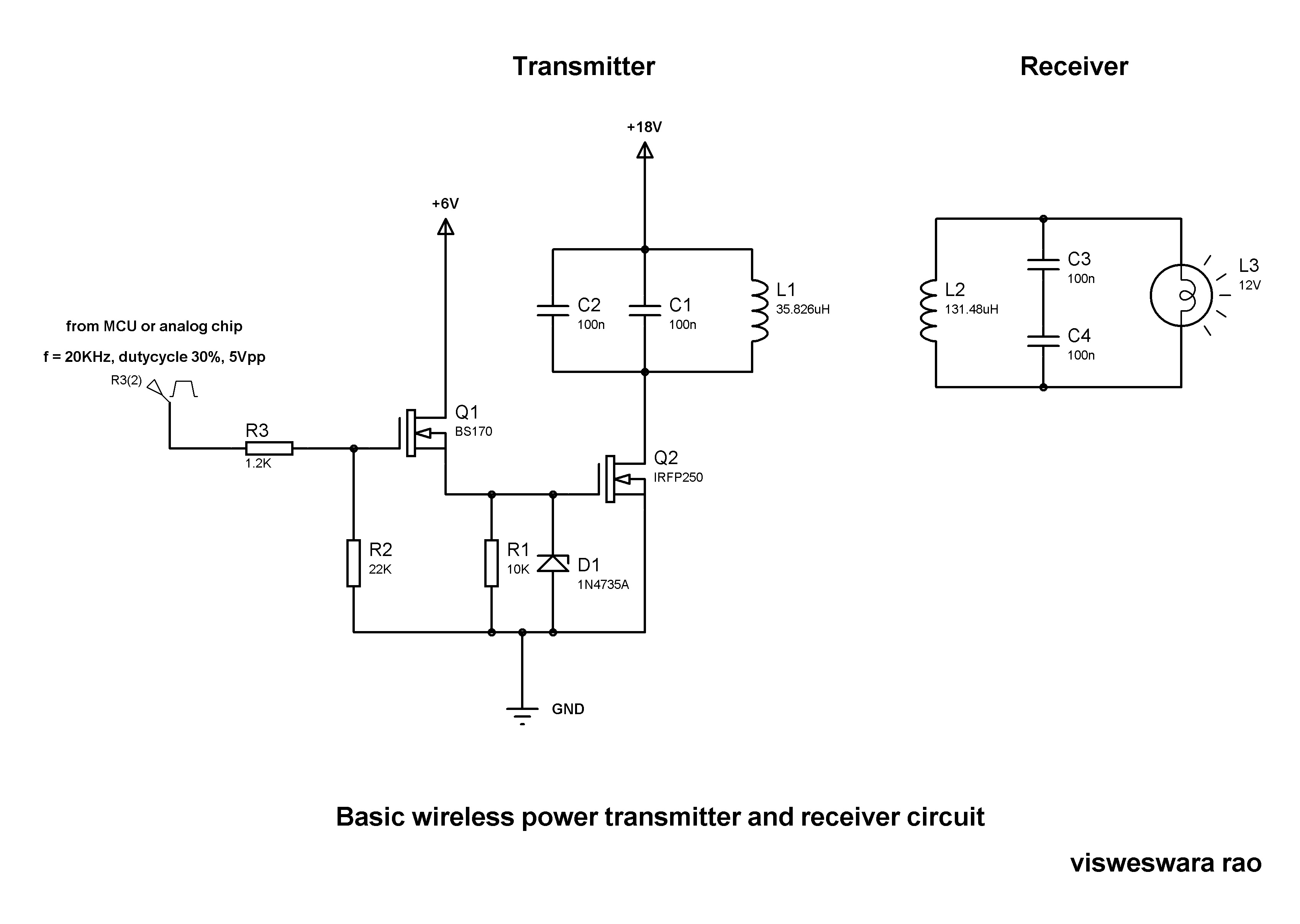
circuit is simple, apply a pulse of 20KHz, 30% duty cycle of 5Vpp  use MCU or analog chip or opamps or schmitt trigger circuit.

BS170 is a lower power MOSFET serves as a gate driver for the power MOSFET IRFP250N,  D1 (1N4735A) a 6.2V zener so the gate to source voltage (Vgs) is always less than 6.2V.   L1 and C1 forms a tank circuit that resonates with a frequency of 59.457KHz. (transmitter )

resonating frequency   of both transmitter and receiver must be same f1 = f2 = 59.457KHz

therefore     1/(2π√(L1C1)  = 1/(2π√(L2C2)

(L1C1)  =  (L2C2)

therefore C2 = 54.4965nF

receiver must be detuned to the frequency using LC tank  formed by L2 = 131.48uH  therefore C2 = 54.4965nF (no 50nF, 1nF cap’s in my lab so i used 2 of 100nF  capacitors connected in series that forms equivalent capacitance of 50nF which is little close to 54.5nF.

note:  the capacitors must be type of polyster or polysulphide and atleast 200V rated..

here is my setup:

setup

Coils

Advertisement

LDR light switch

This is a LDR operated switch circuit, the LED’s ON when no light is present in the room.

circuit diagram and my construction pictures:

WP_20160129_006
LDR light switch
LDR Light Switch
LDR Light Switch

LDR (light dependent resistor) is a passive optical transducer, the resistance of LDR decreases with increase in light intensity, LDR or photoresistor is applied in light sensing detecting circuits, light or dark activated switches.  The resistance of LDR is in the order of few MΩ in the dark and few hundreds of Ω in light….

working: RV1 (variable resistor) sets the reference voltage at the non-inverting pin(V+) of opamp(LM358).  LDR and R1(10K) forms voltage divider network ,  the voltage at the inverting pin(V-) of opamp is low when the LDR in dark , the LDR resistance in the dark is around 10MΩ so the less the voltage drop across the R1(10K) therefore V- is LOW, the voltage at the non-inverting pin is very high which is also the reference voltage set by the trimmer potentiometer(RV1) .

so, Vout = (V+) – (V-)  ( since V- <<  V+)   therefore Vout =V+  ,  the Vout is high, the MOSFET comes into conduction,simply LEDs ON in the dark.. the drain current of the MOSFET  set by the R2 and R3 resistors.  since  the MOSFET is voltage controlled the drain current is high the more the voltage drop across the R3 which is Vgs (gate to source voltage). the Vgs of the MOSFET must be greater than the threshold voltage(2.5V for NTD4963).

D1-D6 are the power LED’s , R4-R9 current limiting resistors, c1 and c2 are decoupling cap’s to remove noise.