IR emitter:
It is a LED emits infrared light (940nm typically) applications of IR LED: like optical counters, free air data transmission, infrared remote control, card readers , etc….
photodiode (type of optical transducer)
photodiode is a high speed diode used to convert current to voltage, it is reverse biased with constant voltage.
Sensor module circuit diagram:
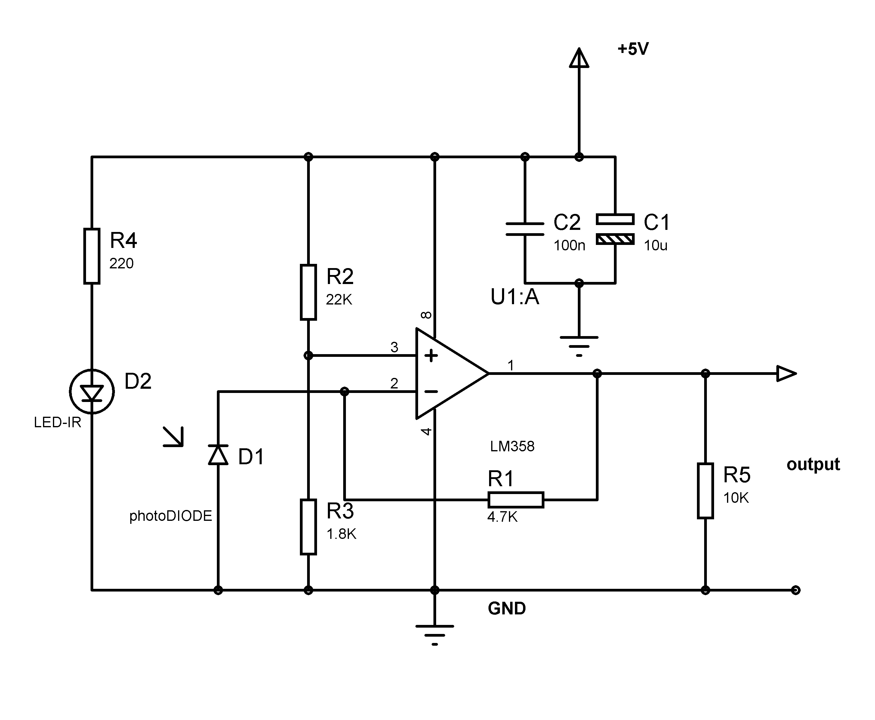
TCRT5000 sensor
opamp LM358
R2 and R3 for biasing the non-inverterting terminal of opamp(LM358), voltage at non-inverting terminal = Vin(1.8K)/(22K+1.8K) = 0.378V (378mV).. that is also the voltage at the pin1 of opamp with refered to ground(GND) when no IR light on photodiode. when full IR light on photodiode the Vout = 3.5V (which is max)
R1 sets the reverse bias voltage across D1(photodiode), in this condition the current flowing through the D1 is in the range of nA typically.
R4 sets the constant current that flows through the IR-LED D2
the forward voltage range is around 1.25 to 1.5V typically, the max current it can handle is 60mA so R4 = (Vin-1.25)/20mA = 187.5ohms if Vin = 5V (220ohms on board)
C2 and C1(decoupling caps) C1 electrolytic reduces the noise voltage created by the low frequency and mid frequency and C2 the low ESR ceramic cap reduces the high frequency noise in power supply lines
here is my construction, it looks ugly, ahh but working fine 😀

the output of sensor module connected to the scope, as you can see the voltage varies, the photodiode starts conduction when the IR light from the emitter is reflected on it, Vout is proportional to the current that flows through the photodiode.
