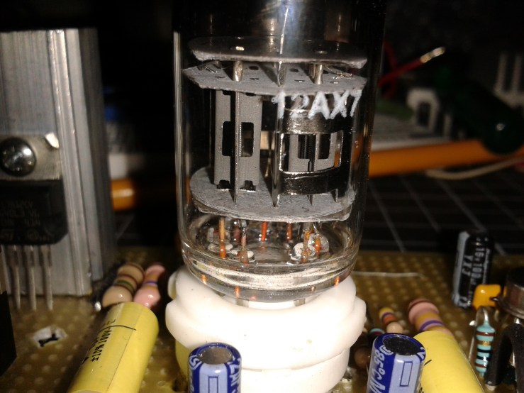
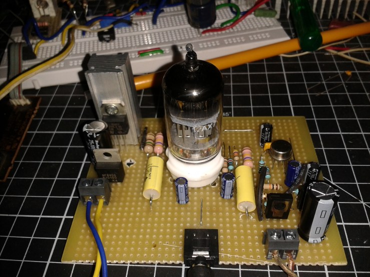
I always wanted to build vacuum tube or valve amplifier. finally I made one hybrid amp. just combined both valve and solid state. For the preamp section I have used 12ax7(dual triode) and for the solid state I built opamp based power amp configured in unity gain..
This is the low power version and I’m sure I am going to build medium power amp delivers atleast 5-10watts to the speaker and no solid state 😀
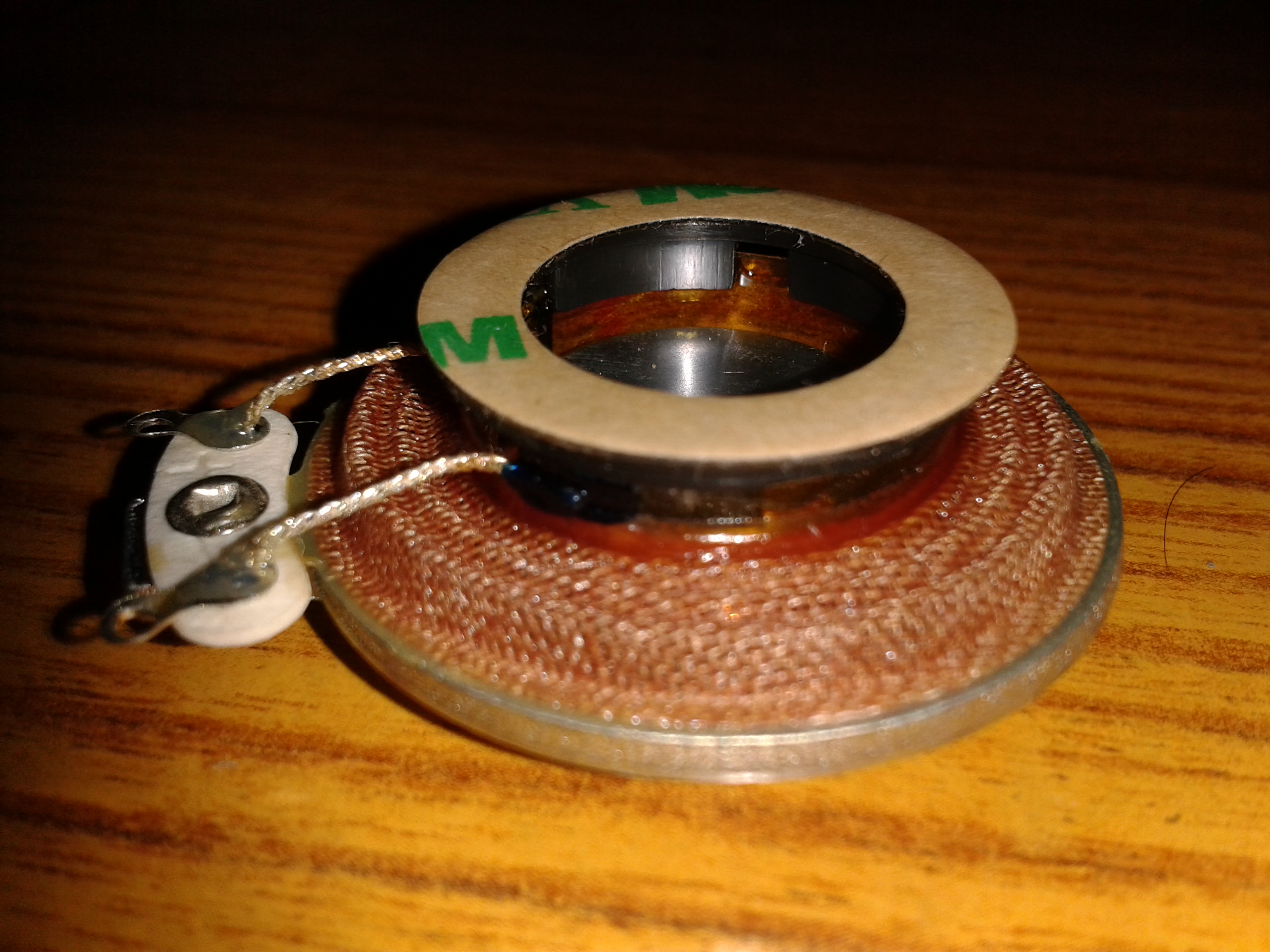
Exciter is also known as bodyshaker, Audio Exciter is just basically a loud speaker without a membrane, and it consists of voice coil , oscillating mass and mounting ring/plate. If the audio/music signal is applied to the contact pins of the voice coil, the oscillating mass starts shaking with the frequency of the applied music, the oscillation is transmitted to the mounting ring and from there on to the surface the exciter sticks to, thus the excited surface emits the music signal.
For testing the audio exciter I did built a small opamp based amplifier which delivers 2Watts rms at 6ohms impedance
This amplifier circuit is nothing new. and you can find a better one here (discrete transistor amp)
This is a simple project, called LED candle. I will be using yellow LED’s of 2 and a simple PWM code that runs on AVR (ATmega328p) chip make’s the LED flickering that almost looks like candle. 😛 for candle I will be using LED’s+translucent paper.
LED candle
circuit:
code is very straight , Simple PWM code runs on ATmega48/328p
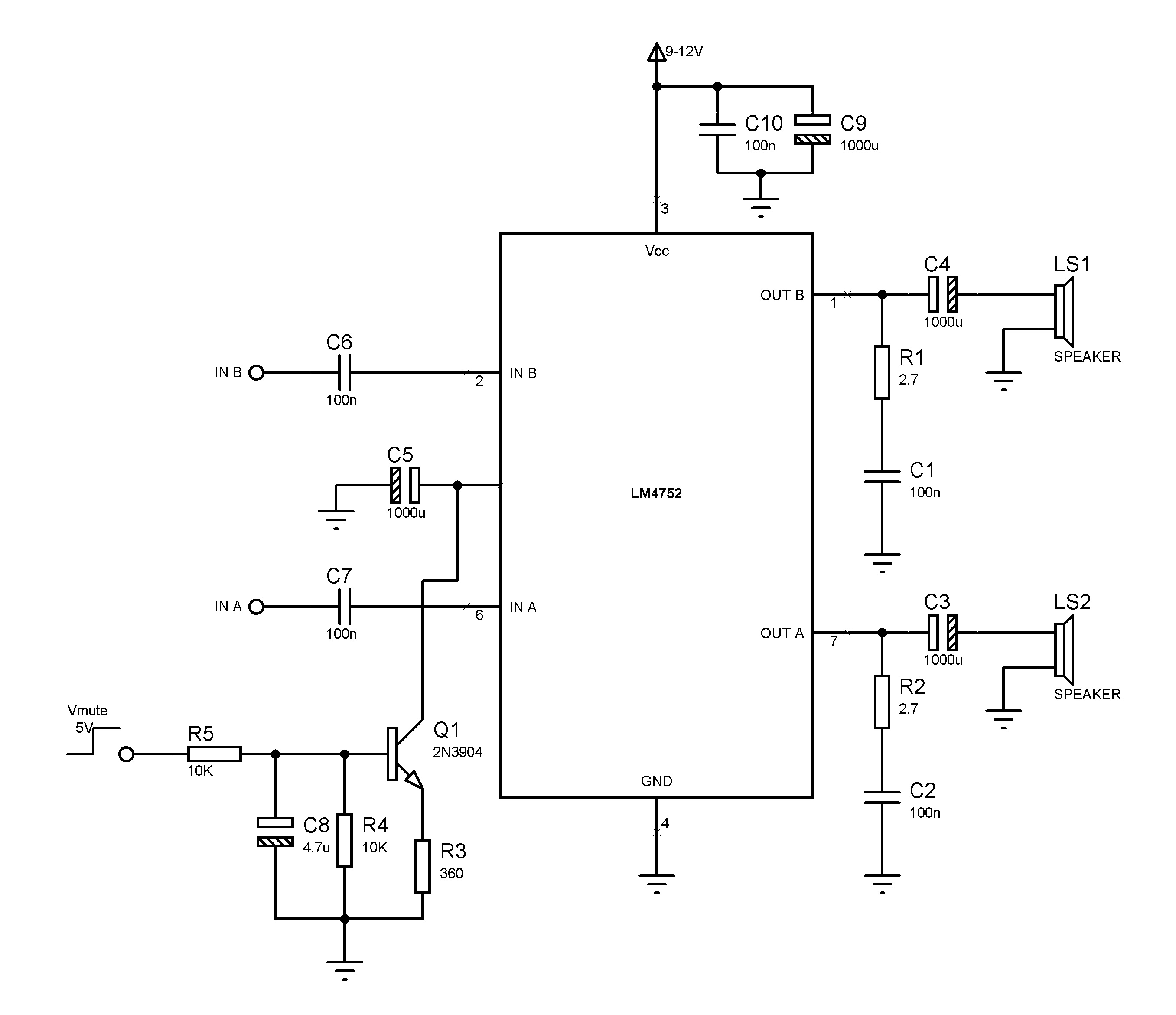
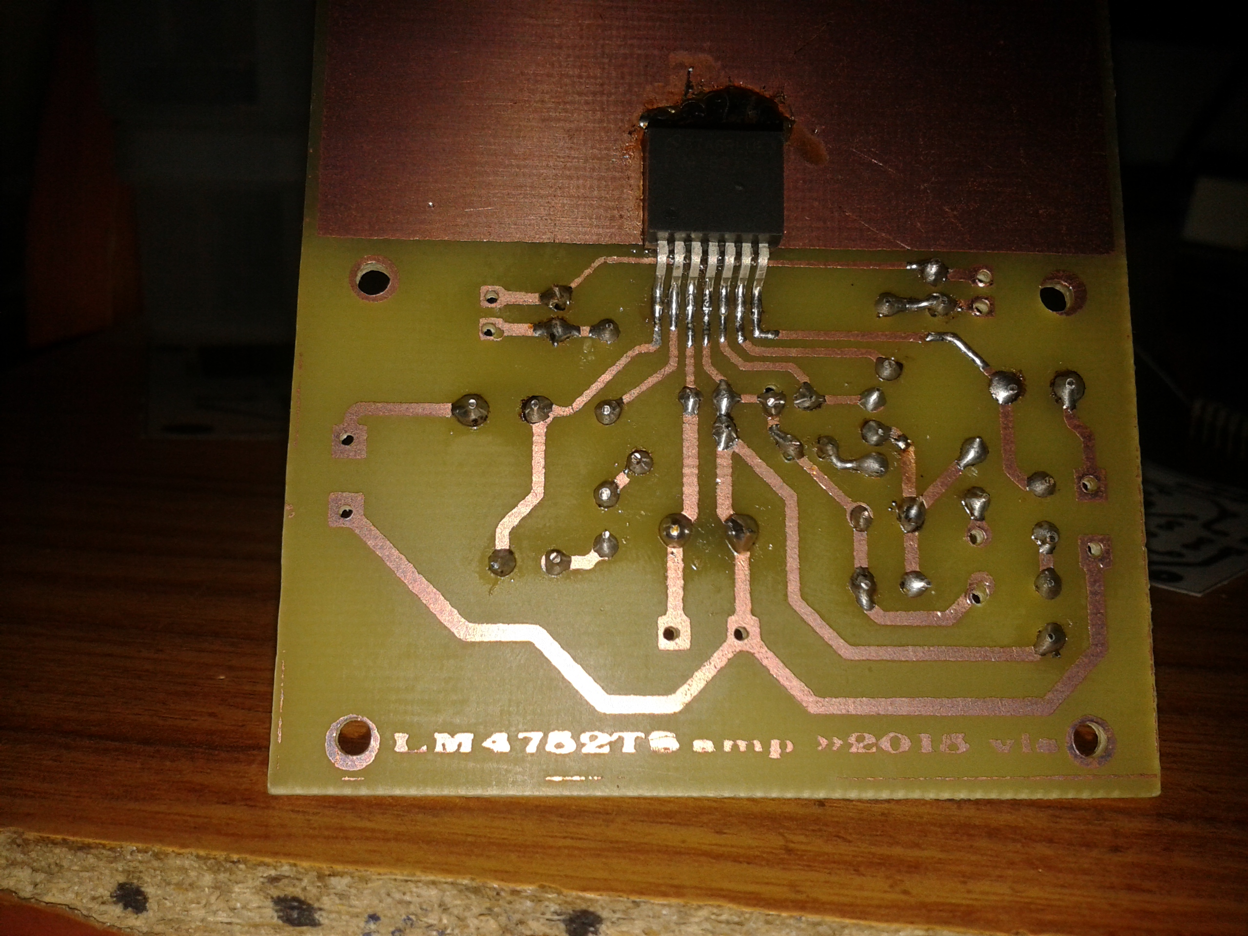
LM4752 is a stereo audio amplifier capable of delivering 11watt per channel of continuous average output power to a 4Ω load, or 7W per channel into 8Ω, using a single supply at 10% THD+N. A simple mute function can be implemented with the addition of a few external components.
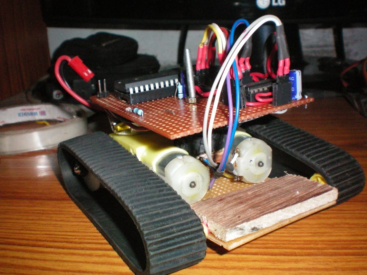
Mini tank robot was my one of oldest project. I built it for fun, no use only for fun. I did used ADXL335 accelerometer for inclination detection , AVR microncontroller (ATmega164P) for processing and controlling and L293D motor driver Chip and BO series motor.
master-slave robot arm or teleoperator, this is one of my oldest project which I was built in 2012, For this simple application I did used NE556 IC to control Servo motors, It is a dual timer chip and yep brother of very famous chip called NE555, NE556 dual timer chip, one timer configured in astable mode and output of it is connected to another timer which is configured in monostable and the pulse width is controlled by simple potentiometer or variable resistor which is connected in monostable circuit(RC network), Monostable output is a control signal further conneted to control terminal of analogue servo motor.
Master_arm (potentiometers as position sensors) wooden arm
master arm(potentiometers as position sensors)
Slave_arm with cheap servos
slave_arm with servo’s
Control circuit using NE556 dual timer chip and some other passive components
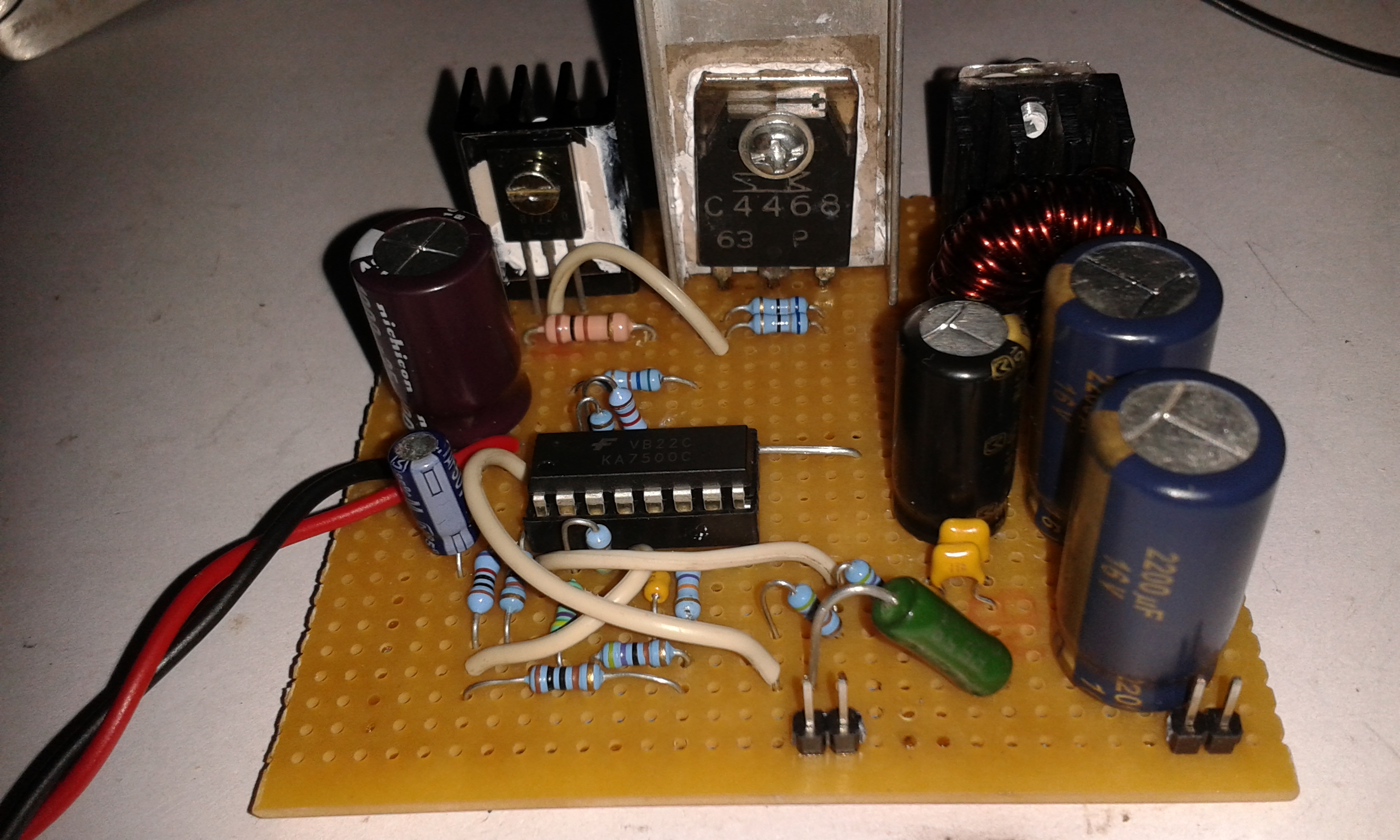
This buck converter/step down circuit is based on KA7500c SMPS controller chip,
the following circuit is from the reference design you can find the details of the circuit and calculations from the document. This is one of the application circuit built around with KA7500C, this buck converter can suply a load current of 5.75Ampere at 5V we could also use TL494 or KA7500c both are same in operation/ratings. The recommended operating voltage range is 7V to 40V DC and the power source i am using for this is a old laptop power supply adapter rated 18V,3.7A. , however the maximum input current the circuit draws is 2A at full load.
buck converter can supply load current of 5.75A at 5V and the short circuit current is 7Ampere. the maximum output is 5V×5.75A, the ripple voltage at max power out is 94mV and input power is 18V×2A and the efficiency(η) calculated
η = output power/input power = 5×5.75/18×2
η = 79.86%
Note: C1,C2,C3 are the low ESR electrolytic capacitors add 2 of 100nF,50V rated ceramic capacitors in parallel to C1,C2,C3, to reduce the high frequency noise.
L1, FS-1RN series toroidal cores made from iron powder (26) for creating inductors, FS-1RN core or similar you can get this one from old desktop PSU’s. here is a useful link of toroids, one of my friend Mr William helped me in selecting toroidal core, thanks to him.
Q1 , Q2 are2SB772 2SC4468 they are audio transistors, can be used for switching applications, linear.
Simple buck converter and nothing fancy the Schematic is straight from the datasheet, 5V, 1A output. this is the small application of buck converter yeah ATtiny84 LED board.
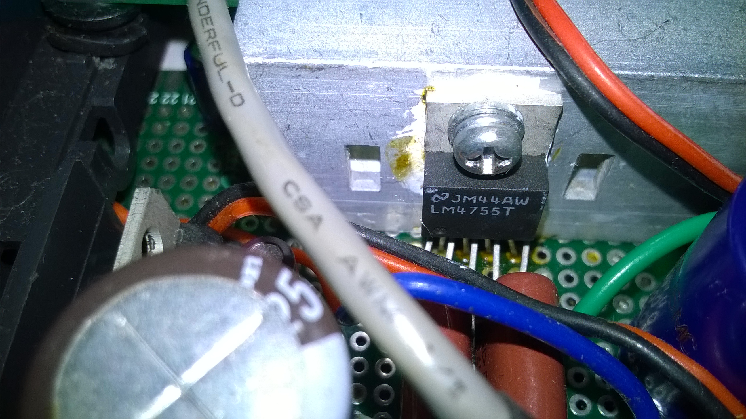
I built this amplifier for my iPod, amp circuit based on LM4755 chip, stereo audio amp capable of delivering 11watt per channel of continues average power output to a 4Ω using a supply of 24V at 10% THD. It is designed for single supply operation.
Features:
Wide supply range 9V-40V
Drives 4Ω and 8Ω loads
Integrated Mute Function
Minimal External Components Needed
Single Supply Operation
Internal Current Limiting and Thermal Protection
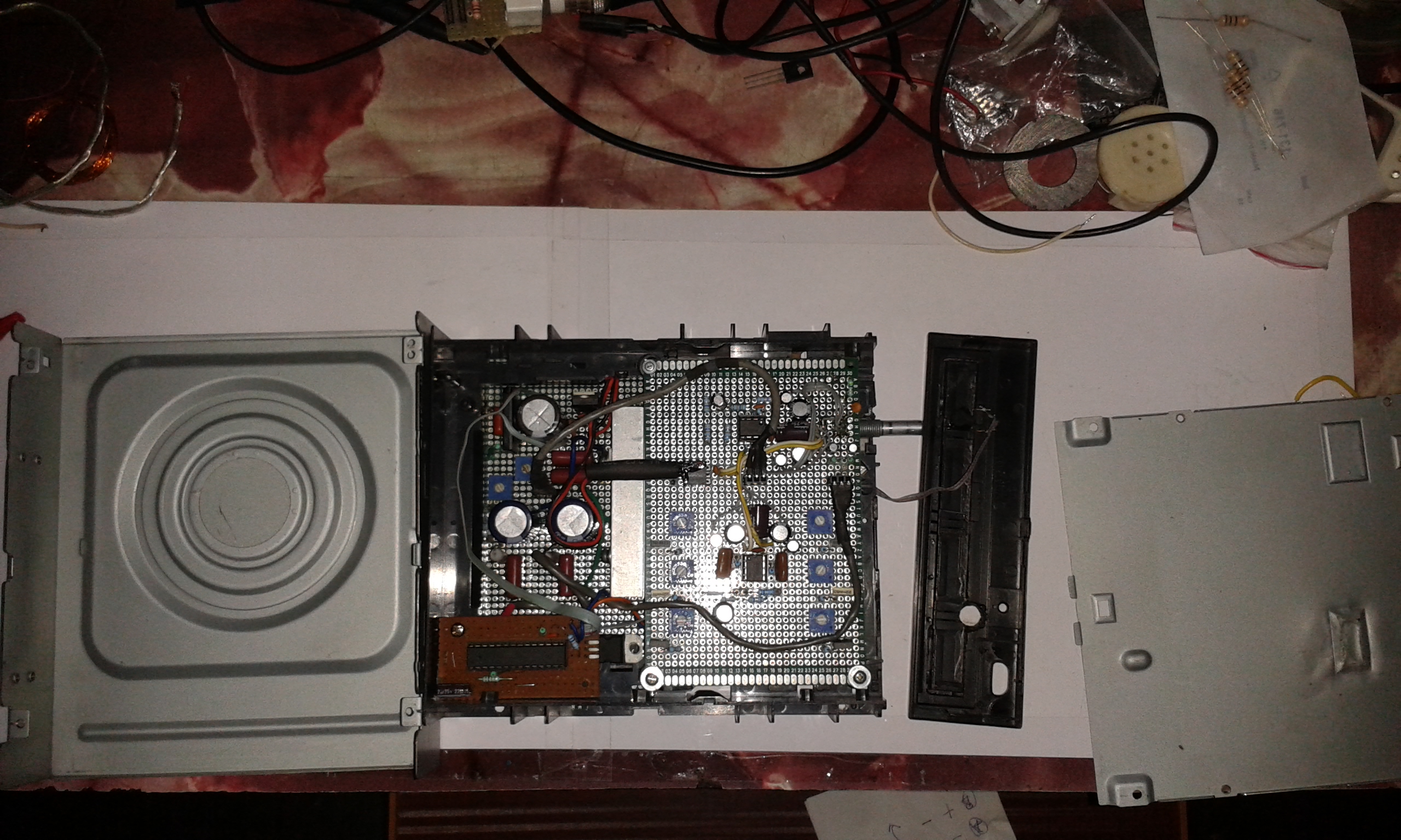
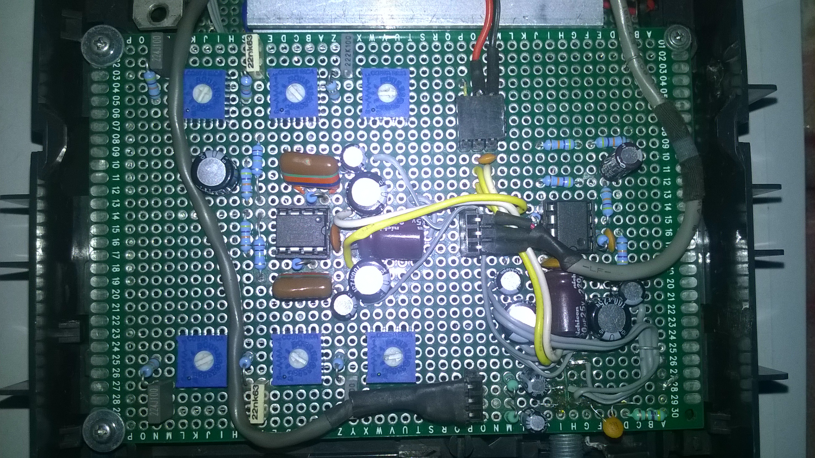
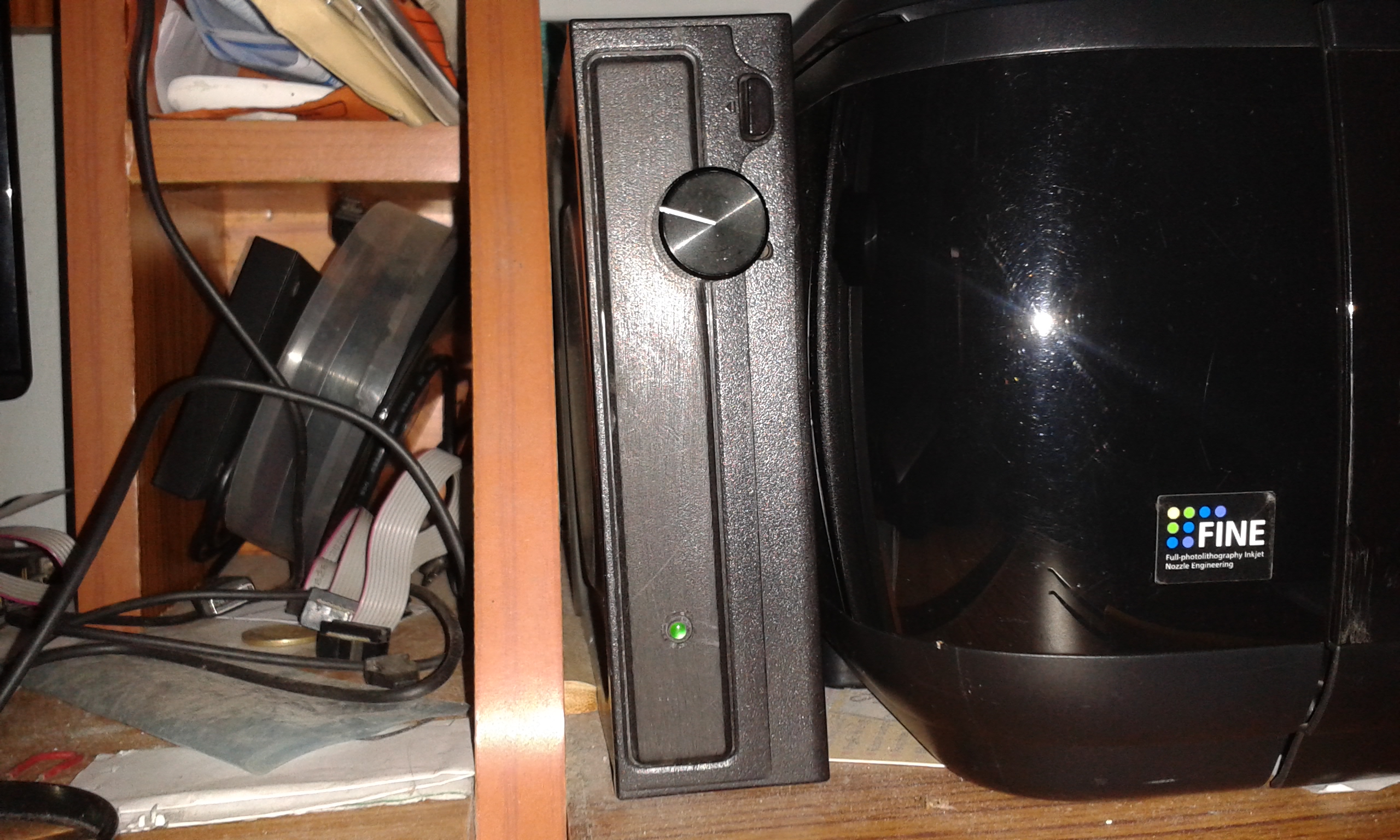
Construction- DIY LM4755 amp
This amp, primarly used on my desk. So it needs to look good, for the enclosure i used old dead CD-ROM case.
for tone control and preamplifier I used OPA2134 (dual opamp) chip.
preamp is 1.5dB gain that works with single power supply. and the tone control to boost or reduce the particular audio frequencies, simple RC filter circuit + preset/VR to control the Signal level of particular freq.
Volume indicator Indicates the level of audio signal.(this project is under construction.. will update soon )
INPUT devices: microphone OUTPUT: LED bar graph processing: AVR (ATmega32A)
My construction:
microphone pickup’s the audio signal and BC546 preamp amplifies the signal to the level 1.8Vpp max, so that ADC can read. BC546 collector feedback bias circuit.
audio fed to the ADC pin of ATmega32A
aaded voltage regulator (2sc1383 + 5V6 zener), we can also use LM7805 regulator.